Thursday, 27 March 2014


Configuring A Dfs Root

To create a Dfs Root, an existing share can be used or a new one can be created. To use the Es-Net share as a Dfs root, click on Start.Select Administrative Tools. Select Distributed File System. This is the Dfs management console. To create a new Dfs root right-click on Distributed File System. Select New Root. The New Root Wizard will appear. Click on Next to continue. Select Stand-alone root to create a new Stand-alone root. Click on Next to continue. The name of the host server must be typed in or browsed for. Click Next to continue. The root name of the folder to share
must be typed in. Click Next to continue. This is the summary page. If all settings are correct then click on Finish to create the new Dfs root. The new Dfs root is displayed in the Dfs management console. Dfs links can now be added to the new Dfs root.


Dfs Replication

Using Domain-Based Dfs, the Dfs root structure can be stored on more than one server. The Dfs root folder will still be accessible if one of the servers goes down. The location of the Dfs root server is published in Active Directory and can be found easily by using its DNS name.In order to use Dfs replication, two or more domain servers are required. The domain es-net.co.uk has two Domain Controllers; Admin1 and Admin3. Open the Dfs management console. Right-click on Distributed File System to create a New Root. Select New Root. The New Root Wizard will appear. Click on Next to continue. The Host Domain for the Dfs root is going to be ES-NET.CO.UK. Click Next to continue. The shared folder Es-net is going to be used for the Dfs root. The Dfs root name is going to be Es-net and will be accessed using the UNC path, \\ES-NET.CO.UK\es-net. N.B. The location of the server isn’t needed, since Domain-based Dfs makes use of DNS. Click Next to continue. Check the summary page. If all settings are correct then click Finish.  The new Dfs root appears in the Dfs management console. To create a root target on ADMIN3, right-click on the Dfs root. Select New Root Target. Type in the name of the second server to host the Dfs root, N.B. This has to be a domain server. Admin3.ES-NET.CO.UK will also host the Dfs root. Click Next to continue. The share Es-net on admin3 will also be used to host the Dfs root. Click Finish to close the wizard. The \\ES-NET.CO.UK\Es-net Dfs root is displayed in the management console. The Dfs root is stored on two machines; admin1 and admin3. Once configured correctly, if either of the servers goes down the Dfs root will still be accessible. Information contained in the root folders needs to be replicated. To configure replication right click on the DFS root.  Click Properties. Click next to continue. Before replication can take place a folder will need to be selected  as an initial master. Select \\admin1\es-net. Then click next.Click Topology.
  • Ring: files replicate to computers in a circular configuration.
  • Hub and Spoke: One computer is designated as the hub. All other connected computers are spokes. Hub replicates with the spokes and vice versa, spokes never replicate directly with each other.
  •  Full Mesh: Every computer has a connection to every other computer. Files created on one computer replicate directly to all computers.
Select Custom. Click Finish to continue. Connections will have to be created before replication can be started. Click OK. Right Click the DFS root.  Select Properties.  Select Replication.  Select Customize.  Select New.  Select Servers to be connected. Click OK to continue.


Configuring Dfs Fault Tolerance

Although the Dfs Root is fault-tolerant, if any links inside the Dfs go down then they will be lost until the server is recovered. To create a fault-tolerant Dfs link, right-click on the Dfs root.Select New Link. Type a Link name and the location of the Target. Accounts will link to \\Admin1\accounts. Click OK to continue. The new link is displayed in the Dfs management console. If admin1 was to go down then the root folder would still be accessible, but Accounts would be unavailable. To create a new Dfs link replica right-click on Accounts. Select New Target. Type in the network location of the folder to be used as a replica of Accounts. Click OK to continue. Accounts will point to both shared folders \\admin1\accounts and \\admin3\accounts allowing for fault-tolerance. To enable replication click on Yes.Replication wizard starts Click on next to continue. Before replication can take place a folder will need to be selected  as an initial master. Select \\admin1\accounts. Click next to continue. Click on Topology.  Select Custom.  Click on Finish to continue. Connections will have to be created before replication can be started. Click OK.
Right Click on Accounts.  Click on Properties.  Select Replication.  Select Customize.  Select New.   Select the servers to connect.    Click OK to continue.  When all connections are complete, click OK. Replication is enabled. Right click accounts to check its status. Select Check Status.  A green tick indicates that all is as it should be.   Further links can now be added.

Configuring Dfs Fault Tolerance

Although the Dfs Root is fault-tolerant, if any links inside the Dfs go down then they will be lost until the server is recovered. To create a fault-tolerant Dfs link, right-click on the Dfs root.Select New Link. Type a Link name and the location of the Target. Accounts will link to \\Admin1\accounts. Click OK to continue. The new link is displayed in the Dfs management console. If admin1 was to go down then the root folder would still be accessible, but Accounts would be unavailable. To create a new Dfs link replica right-click on Accounts. Select New Target. Type in the network location of the folder to be used as a replica of Accounts. Click OK to continue. Accounts will point to both shared folders \\admin1\accounts and \\admin3\accounts allowing for fault-tolerance. To enable replication click on Yes.Replication wizard starts Click on next to continue. Before replication can take place a folder will need to be selected  as an initial master. Select \\admin1\accounts. Click next to continue. Click on Topology.  Select Custom.  Click on Finish to continue. Connections will have to be created before replication can be started. Click OK.
Right Click on Accounts.  Click on Properties.  Select Replication.  Select Customize.  Select New.   Select the servers to connect.    Click OK to continue.  When all connections are complete, click OK. Replication is enabled. Right click accounts to check its status. Select Check Status.  A green tick indicates that all is as it should be.   Further links can now be added.


Thursday, 20 February 2014


400 Android Games Collection + HD + Emulators [PAID APPS ONLY]


Description

--------------------------------------------------------------------------------------------

The 400 most popular games from Android Market! This torrent includes all games

from my other torrents. If you liked my others collection you gonna love this, 

it's definitely worth to download "again".                                    


My 300 android collection was included more than 50 games who was not able to  

install - all this is now deleted. So this torrent includes more than 150 games

than my 300 Android games collection!                                          

--------------------------------------------------------------------------------------------

The Torrent is including:                                                      


400 Android Games - Paid Only                                                  

7 Android Emulators - Paid Only - Free roms can be found at RomHustler.net     

ASTRO Manager Pro - Just install and your ad is disable                                                                                           


Please check in utorrent to know the GAMES!                                    

--------------------------------------------------------------------------------------------

Install apps with the .apk extension:                                          


1) Go to settings - applications - enable the 'unknown sources' option.        

2) Put the .apk files somewhere on your SD card.                               

3) Open your file manager on the device (like Astro Manager from market). You can

delete the Ad using the key in ASTRO.Manager.Pro map.                          

4) Select a .apk file.                                                         

5) If you get the 'complete action using' pop-up, choose 'package installer'.  
Click Here          


Need For Speed Rival

DESCRIPTION

Erase the line between single player and multiplayer in this street-racing rivalry between Cops and Racers.

Seamlessly join a world where your friends are already racing and chasing. Forget isolated game modes. There are no lobbies; no waiting. You and your friends can all share the same race as paths cross and experiences merge.
• All-drive: Imagine your race and your friend’s pursuit colliding—creating a world where no two events feel the same. Don’t want to play with others? Then simply choose to make Redview County yours alone and dominate the advanced Racer and Cop AI.

• High-stakes rivalry: Racers are lone wolves out for glory; driving agile cars built for high-speed racing and epic chases. Cops work in teams to hunt down and bust racers using the full power of the police force. Switch roles whenever you like, and watch the stakes grow through a new scoring system that puts your speed points on the line.

• Next-gen racing: Experience speed that you can truly feel in the fastest racing game around, powered by the Frostbite 3 engine. Every detail of the game world is rendered in stunning, high-definition graphics. Race and chase in snow, hail, rain, dust storms and heavy fog.

Download Link

http://kickass.to/need-for-speed-rivals-skidrowcrack-t8184155.html#main

Saturday, 4 January 2014

Transmission Control Protocol/Internet Protocol (TCP/IP)

In order for communication to occur on a network  all parties must use a common language. In IT networks this is known as a protocol.  There are many different protocols available for computer networks. The most common and widely used being TCP/IP.

TCP/IP is the standard protocol that is used on the internet. In order for any network to access the internet you must use the TCP/IP protocol suite. TCP/IP is required by Active Directory. For this reason, TCP/IP is the default protocol for Windows XP and 2003.

Protocols

Reference is often made to the TCP/IP stack. This consists of layers of mini applications which perform the discrete job of  sorting and filtering the data packets picked up by the NIC and then passing the packet on to the next layer for further processing. Eventually a coherent message pops out of the top of the stack into the operating system for the user to read. The reverse is also true i.e. converting of the reply into data packets that can be sent over the network media.
The layers in a TCP/IP stack write headers for network messages as well as decoding them.  Each level in the stack adds a portion to the network packet which its counterpart in the receiving computer will understand.  Strictly speaking, the NIC isn’t part of TCP/IP, but protocols are bound to a particular adapter.
At the receiving computer, the headers are stripped off as they pass up through the  TCP/IP stack until only the bare payload is presented to the user.

The DOD Four Layer Model

Transmission Control Protocol/Internet Protocol (TCP/IP)TCP/IP is often referred to as the TCP/IP protocol suite. TCP/IP is in fact a group of protocols/applications working together to provide network communication. TCP/IP was invented by the US Department of Defence (DOD) to allow machines to communicate over a network. It is a simpler model than the 7 layer OSI model.  The different components of TCP/IP all function at different layers. These layers group the different components into four different categories.

The Application Layer

The Application Layer contains the applications that use TCP/IP such as Internet Explorer and Outlook.  The Application Layer also contains Application Programming Interfaces (API) such as Winsock, which enables applications to use TCP/IP.

The Transport Layer

The Transport Layer is responsible for the transfer of data on the network.  There are two different transport protocols TCP and UDP. Both protocols provide transport but work in different ways.

Transmission Control Protocol (TCP)

TCP is a connection-orientated protocol. Both sides confirm that the data is being sent and received.

User Datagram Protocol (UDP)

UDP is a connectionless-orientated Protocol. Both computers presume the other side has received the data.  As an example, name resolution uses UDP. If the query fails then a TCP name query is made.

The Internet Layer

To send data the sender must have a method of distinguishing the recipient. This is called an IP address and they take the form of a unique number on the network . The Internet Protocol is responsible for these addresses.  The Internet Control Messaging Protocol (ICMP) is used to test connectivity between machines by sending ICMP messages using the PING command.  The Internet Group Messaging Protocol (IGMP) is used to send data to groups of machines, e.g. Streaming Video. This is known as Multicast.  The Address Resolution Protocol (ARP) is responsible for changing an IP address into the network card’s physical address. Every network card has a unique physical address hardwired into the card itself which is needed for communication on a network.

The Physical Layer

The Physical Layer is responsible for the actual physical media and how the data is sent to another machine, e.g. Fibre Optic, ATM.  There are many ways to send data down the cable, the most common technologies for LANs are Token Ring and Ethernet. In order for two machines to communicate they must be using the same technology or be connected via a bridge .

Troubleshooting TCP/IP

These are the two main utilities for troubleshooting TCP/IP:ping – used to test connectivity
ipconfig – used to view IP address information.
Before launching into detailed settings investigation, always check that the hub/switch has power to it, or that the network cable hasn’t been pulled out.
The ping command does the following:
Verifies connections to one or more remote computers by sending ICMP echo packets to the computer and listening for echo reply packets.
Waits for up to one second for each packet sent.
Prints the number of packets transmitted and received.
Each received packet is validated against the transmitted message to check that no data loss occurs.
The first  item to ping is the local NIC. The loopback address is 127.0.0.1. (Pinging “localhost” does pretty much the same thing.). If this fails then either your TCP/IP stack isn’t installed correctly, or the network card is not functioning.
Troubleshooting TCP/IPThe first  item to ping is the local NIC. The loopback address is 127.0.0.1. (Pinging “localhost” does pretty much the same thing.). If this fails then either your TCP/IP stack isn’t installed correctly, or the network card is not functioning.
Note that an address or computer name can be pinged.
Here a computer “jacklap” (ip address 10.1.0.104) can’t be pinged. This doesn’t necessarily imply a connection problem. It may be a name resolution problem, and can be tested by pinging the ip address.
If you can ping your own machine and others on the local network, then try pinging the default gateway. A message such as the one above implies that either the address is a wrong one, or if the report reads destination host unavailable then there may a problem with the gateway machine (router).

Ipconfig

Default gateways or DNS servers can be discovered using the Ipconfig utility.
Typing Ipconfig at a command prompt brings up useful information. No settings can be altered from this window, but it reports the current settings for TCP/IP.
Typing Ipconfig with the /all switch presents additional items such as the adapter’s MAC address and name resolution information.

Internet Connection Firewall

Windows XP ships with a basic built-in firewall. The firewall helps protect the computer from outside attacks on the internet. A firewall controls which network traffic is allowed in and out of a computer. It does this by opening and closing ports.
When communications take place between two machines different port numbers are used depending on the service. As an example a Web Browser will communicate with a Web Server on port 80, which is the default port for HTTP (The language used to display web pages).
There a thousands of port numbers available many of the lower range numbers being reserved for common services. A few of the common port numbers are listed below.
Port 80:    HTTP (Web Pages)
Port 21:    FTP    (File Transfer Protocol)
Port 25:    SMTP (E-Mail)
Port 110:   POP3   (E-Mail)
Port 443:   SSL     (Secure Web Pages)
A hacker can sometimes compromise security on a machine by gaining access to the machine through an unused port. A Trojan horse virus opens a port on a client machine allowing a hacker to gain access to the machine.  A firewall can be configured to allow only specific ports in and out of the computer thus greatly reducing the risk of a cracker gaining access.
Internet Connection FirewallTo enable and configure the Internet Connection Firewall navigate to the properties of your network connection and selected Advanced.
Check the Internet Connection Firewall box to enable the firewall.
And select Settings to configure it.
A list of services allowed to connect to this machine is shown. New services can be added by selecting Add.
And filling out the details for the service.
For example this machine is hosting a Puma chat room server. Click on OK to add the service.
Connections on port 270 are now allowed to connect to this machine.
The Security Logging Tab specifies settings relating to the security log. For example you can log any unsuccessful connections.
The ICMP tab can be used to configure ICMP packets on the computer. ICMP packets are used during ping requests.
The options for the Internet Connection Firewall have been improved slightly for Windows XP Service Pack 2 however the principals remain exactly the same.  Although the firewall is good enough to protect home users, for larger corporate networks and servers a third-party firewall should be used such as Microsoft ISA server.

Configuring TCP/IP

This free lesson will teach you how to configure TCP/IP in windows and how to use the ipconfig command.
To configure TCP/IP click on Start.
Right-click on My Network Places.
Select Properties.
Configuring TCP/IP
Right-click on the connection you want to configure and select Properties.
Highlight Internet Protocol (TCP/IP).
Select Properties.
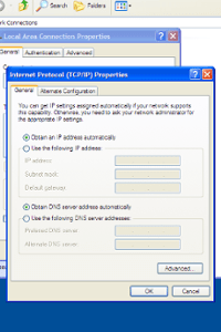
This machine is currently configured to obtain an IP address automatically. Select Use the following IP address and fill out the relevant details.
Additional gateways and IP addresses can be added by clicking the Advanced Button…
..and configuring the appropriate options.

Using the ipconfig command

The ipconfig command can be used to display IP address information from a command prompt
Running ipconfig with /all switch produces a much more verbose display.

The IP Address

Every computer on a network and the internet needs an address. This address is known as an IP address. Two computers can never have the same address.  An IP Address is a group of 4 eight bit binary numbers represented in decimal. Each number is separated by a period, e.g. 10.1.0.1.  Any machines that are connected to a network will each need a unique address. Two machines cannot use the same address.
The IP address is divided into the network ID and the host ID. The network ID represents what network the machine is on. For two machines to communicate they have to be using the same network ID. The host ID represents a unique number assigned to the machine attached to the end of the network ID. For two machines to communicate they need to Have the same network address. They must, however have different host numbers.
A machine can identify which part of its IP address is the host ID and which part is the network ID by using a set of numbers called a subnet mask.

Subnet Masks

As well as an IP address every machine using TCP/IP needs a subnet mask.  The subnet mask splits the IP address into two parts, allowing the computer to identify which part is the network ID and which part is the host ID.
The subnet mask divides the IP address into two parts by using on (1) and off (0) switches. 1 represents a network ID and 0 represents a host ID.
A computer with an IP address of 10.1.0.1 and a subnet mask of 255.255.0.0 would have a network ID of 10.1 and a host ID of 0.1. This is worked out by converting both numbers into binary.
10            .1           .0.          1
00001010.00000001.00000000.00000001
255           .255.            0.               0
11111111.11111111.00000000.00000000
Using the subnet mask, divide the IP address up by using the 1’s to represent the network ID and the 0’s to represent the host ID.
00001010.00000001.00000000.00000001
11111111.11111111.00000000.00000000.
Using this, we can assume that the network ID is 00001010.00000001 (10.1) and the host ID is 00000000.00000001 (0.1).
A subnet mask doesn’t have to be a full octet. It is possible to use a subnet mask that is only a partial octet.
For example 255.255.240.0: This enables the administrator to create custom subnets to divide a private network into several discrete sub- networks

Bit Notation

An easier way of writing an IP address and its subnet mask is by using the form xxx.xxx.xxx.xxx/bits in the mask.  The address 10.1.0.1 with a subnet mask of 255.255.0.0 can also be written as 10.1.0.1/16.
This form of notation shows the number of Bits in the subnet mask, e.g. /8 represents 11111111.00000000.00000000.00000000 or 255.0.0.0.
/20 would represent 11111111.11111111.11110000.00000000 or 255.255.240.0.

IP Address Classes

When TCP/IP first appeared, IP addresses were placed into different classes A,B,C and D. The subnet mask of the machine would be determined by its IP address class.  To determine what class an IP address is , refer to the first octet of the address, e.g. 100 for 100.23.23.1
To determine what class an IP address is , refer to the first octet of the address, e.g. 100 for 100.23.23.1
Class    Subnet Mask                         Host ID’s
A       255.0.0.0                                   16,777,214
B       255.255.0.0                               65,534
C       255.255.255.0                           254
D       255.255.255.255 (Multicast)     N/A
The IP AddressOf the 32 bits available, the bits required for the network ID can’t be used. In a class B network for example this takes away 16 bits, leaving 16 bits for the host addresses. This can be used to make numbers up to 65536 (2 to the power 16). Host addresses using all 1’s or all 0’s are reserved for special use, hence the figure in the above table of 65534.
You have been assigned the address 134.34.0.0/20, how many hosts will you have?
/20 represents the subnet mask of 11111111.11111111.11110000.00000000 (255.255.240.0)
Therefore the Host ID is 0000.00000000, giving a total of 12 host ID’s to play with.
Therefore  (212)-2=4094. So there are 4092 different host ID’s
Why take off 2?
Two host ID addresses are reserved for every network.
If the host ID contains all 0’s it represents the Network it is on and can’t be used, e.g. 10.1.0.0/24 (00000000) is invalid. This is known as the Network Address.
If the host ID contains all 1’s then this represents every computer in the network. This is known as the Broadcast Address, e.g. 194.34.23.255/24 (11111111) represents every computer in the 194.34.23 network.
Reserved addresses:
If the host part of the address is all zeroes, this looks similar to the subnet mask and is called the Network Address. By convention, this address is not used for any host. If the host part of the address is all ones, this represents not a single host but all hosts on that network. It is termed the broadcast address, and it shouldn’t be used for any host.
Although these days you can have any subnet mask, classes are still used when a subnet mask isn’t given. There are  a number of private address ranges available for use in internal networks. These addresses will never be seen on the internet. As internet routers will not pass packets that originate from these addresses.
Class A : 10.0.0.0 – 10.255.255.255
Class B : 172.16.0.0 – 172.31.255.255
Class C : 192.168.0.0 – 192.168.255.255

Custom Subnet Masks

Imagine a scenario where you have been assigned the address range 193.28.34.0 for your company’s network. You need to have 14 separate networks each with ten computers in.
193.28.34.0 is a class C address which means you have 254 hosts but only the one network (the 193.28.34) network.
Considering that you only need 10 hosts and not 254 we can take some of the host ID’s and turn them into Network ID’s. You can do that by creating a custom subnet mask…
We have the 8 host digits to play with. This equates to (28)-2=254 addresses. However we only need 140. Some of the host ID’s can be used as network ID’s.

Routers

Routers are network devices that are used to connect separate networks and to enable network traffic to pass between the networks.  We have seen that machines on separate networks cannot pass data between themselves without assistance.  A router or default gateway passes data to addresses that are not on the senders network.
With the help of a router computers on both networks would be able to communicate. The router is physically connected to both networks and has two IP addresses.
When a client wants to send a packet out on the network it checks the network ID of the destination machine. If it is different from its own it would send the packet to its default gateway.
Routers can communicate with other routers so that network packets can be passed to their correct destinations.
A network packet travelling out on the internet may pass through several routers before reaching its target. Each router forwards the packet on to the next router until it either reaches or fails to reach its destination.

Binary Numbers

The thinking bits of a computer use “flip-flops” to show “up” or “down” or “ on” or “off”. It’s just as easy to think of these as on/off light bulbs. Arrays of these flip-flops are used for storing and manipulating numbers. The point is that they can only have two states like a light bulb. These two states can also be stores as N/S magnets on a hard disk, or pits in foil on CD, or high and low voltages in a cable etc. etc.

Computers similarly use groups of switches to represent numbers and perform calculations. These groups of switches are known as registers and show numbers in Binary form. Denary numbers (which we also call Decimal) use 10 symbols to represent numbers – 0123456789, whereas Binary needs just two symbols 01.
The number of digits in a binary number can be represented by a corresponding number of switches. In computer parlance, these are bits.
A bit is either a 1 or a 0. The different bits in a binary number represent different values which are used to create a number.
Binary Numbers
If the bit is switched on (1) then we use that bit. If the bit is switched off (0) then we ignore it. Add all the (1) switches together, 128+64+16+8+1, and you get the number 217. So the binary number for 217 is 11011001.

Binary Number Examples

11111010      128+64+32+16+8+2=250
00011010     16+8+2=26
11110000     128+64+32+16=240

Transmission Control Protocol/Internet Protocol (TCP/IP)

 in order for communication to occur on a network  all parties must use a common language. In IT networks this is known as a protocol.  There are many different protocols available for computer networks. The most common and widely used being TCP/IP.

TCP/IP is the standard protocol that is used on the internet. In order for any network to access the internet you must use the TCP/IP protocol suite. TCP/IP is required by Active Directory. For this reason, TCP/IP is the default protocol for Windows XP and 2003.

Protocols

Reference is often made to the TCP/IP stack. This consists of layers of mini applications which perform the discrete job of  sorting and filtering the data packets picked up by the NIC and then passing the packet on to the next layer for further processing. Eventually a coherent message pops out of the top of the stack into the operating system for the user to read. The reverse is also true i.e. converting of the reply into data packets that can be sent over the network media.
The layers in a TCP/IP stack write headers for network messages as well as decoding them.  Each level in the stack adds a portion to the network packet which its counterpart in the receiving computer will understand.  Strictly speaking, the NIC isn’t part of TCP/IP, but protocols are bound to a particular adapter.
At the receiving computer, the headers are stripped off as they pass up through the  TCP/IP stack until only the bare payload is presented to the user.

The DOD Four Layer Model

Transmission Control Protocol/Internet Protocol (TCP/IP)TCP/IP is often referred to as the TCP/IP protocol suite. TCP/IP is in fact a group of protocols/applications working together to provide network communication. TCP/IP was invented by the US Department of Defence (DOD) to allow machines to communicate over a network. It is a simpler model than the 7 layer OSI model.  The different components of TCP/IP all function at different layers. These layers group the different components into four different categories.

The Application Layer

The Application Layer contains the applications that use TCP/IP such as Internet Explorer and Outlook.  The Application Layer also contains Application Programming Interfaces (API) such as Winsock, which enables applications to use TCP/IP.

The Transport Layer

The Transport Layer is responsible for the transfer of data on the network.  There are two different transport protocols TCP and UDP. Both protocols provide transport but work in different ways.

Transmission Control Protocol (TCP)

TCP is a connection-orientated protocol. Both sides confirm that the data is being sent and received.

User Datagram Protocol (UDP)

UDP is a connectionless-orientated Protocol. Both computers presume the other side has received the data.  As an example, name resolution uses UDP. If the query fails then a TCP name query is made.

The Internet Layer

To send data the sender must have a method of distinguishing the recipient. This is called an IP address and they take the form of a unique number on the network . The Internet Protocol is responsible for these addresses.  The Internet Control Messaging Protocol (ICMP) is used to test connectivity between machines by sending ICMP messages using the PING command.  The Internet Group Messaging Protocol (IGMP) is used to send data to groups of machines, e.g. Streaming Video. This is known as Multicast.  The Address Resolution Protocol (ARP) is responsible for changing an IP address into the network card’s physical address. Every network card has a unique physical address hardwired into the card itself which is needed for communication on a network.

The Physical Layer

The Physical Layer is responsible for the actual physical media and how the data is sent to another machine, e.g. Fibre Optic, ATM.  There are many ways to send data down the cable, the most common technologies for LANs are Token Ring and Ethernet. In order for two machines to communicate they must be using the same technology or be connected via a bridge .


Tuesday, 26 November 2013

Configure

Security Overview

The object  of security is to protect data and it’s availability being compromised by malice or by accident.  In Windows there are two main strands to security – specific access permissions and authentication.  Specific permissions can be applied to users, groups, or resources.  Authentication confirms to the machine or network that a user has an account with permissions to log on.Individual servers and workstations need protection. As do the connections between them – especially if the connection is over the internet. In addition to making organisational precautions through software settings, attention should be given to the physical security of the system. The items illustrated can all be physically removed from a machine or indeed a building and therefore may require physical security.
A last theme of security is that of Auditing. This allows the administrator to view the history of who has attempted to access a resource and whether they succeeded.  Security can be set at the level of the individual machine or across a wider unit such as a domain. In each case the principles of securing the hardware, software and user access apply.

Security Considerations

Passwords are a principal device for restricting access to a machine or network. However, passwords can be guessed or stolen. To guard against theft or discovery, passwords should be changed frequently. Windows can enforce a password changing policy upon its users.  To counter guessing, quite simply, the passwords need to be made as long and as complex as is practicable.
A single letter password chosen from a…z might be guessed after 26 attempts. A two – letter password  has 26 times more possibilities (676). The following table shows this sequence of increasing complexity:
1 – 26 possibilities
2 – 676 possibilities
4 – 456976 possibilities
8 – 208827064576 possibilities
For passwords using a…z
Windows permits passwords of up to 127 characters, but recommends at least 7 for a password.
A single letter password chosen from a to z gives a base of 26 elements, but if the choice of elements includes upper-case letters and other symbols, thus the complexity level is increased significantly, and the password integrity is strengthened.  The length and the composition of a user’s password can be specified in a security policy, either for an individual machine or for a domain.  The lifetime of a password can also be set by this policy and the reuse of old passwords may also be prevented.
In summary, for a password to be strong and difficult to crack, it should:
  • Be at least seven characters long.
  • Be significantly different from your previous passwords.
  • Not contain your own name or user name. (Nor the name of spouse, children, pets etc.)
  • Not be a common word or name.
  • Have at least one symbol character in the second through sixth positions.
  • Contain Letters a-z, A-Z, Numerals 0, 1, 2, 3, 4, 5, 6, 7, 8, 9 and Symbols` ~ ! @ # $ % ^ & * ( ) _ + – = { } | [ ] \ : ” ; ‘ < > ? , . /
There are many facets of computer operation which need protection from unwarranted interference.
Files
Files need to be read by some users, modified by other users, backed up by yet other users, encrypted by owners and hidden from most! This is apart from needing to create files, delete files and share them across a network. Each of these is possible simultaneously in Windows because of the facility to set individual detailed permissions.
Granting Permissions
There is a permission for viewing and changing permissions on files and folders. When new resources are created, this permission needs to be configured carefully.
Domains And Sites
Permissions for access to larger units  such as  a domain are separate from those granted for local resources. Changes to one aren’t reflected in the other. For example if a user’s account is disabled for a local resource, the domain account may still be active.
Configuration
Settings for users or sites can be made so that such things as Control Panel and Administrative Tools are not available to a user or range of users. This is used to enhance security, but it can also be used to enforce corporate themes and identities across users’ desktops.
Installing Applications
The facility to install applications should not be distributed lightly. Non-standard, unsupported or defective applications can be a drain upon available technical support time, and interfere with multi-layer processes. This facility can be controlled quite closely with Windows.
Network Access
Rogue servers and users can attach themselves to a network, pretending to be something they’re not and gain access to private data. Long cable runs and internet links are weak points for the monitoring of traffic – hence a need for encryption.

Kerberos v5

Kerberos V5 is the primary security protocol for authentication within a domain. (Windows can use others such as SSL, TLS & NTLM.) The Kerberos V5 protocol verifies both the identity of the user to the network services and the service to the user. This form of verification is known as mutual authentication. Kerberos is named after the legendary 3-headed hound which guarded the gateway to Hades, the ancient Greek version of Hell.
The Kerberos V5 authentication mechanism issues tickets for accessing network services. These tickets contain encrypted data, including a users encrypted password and unique SID  that confirms the user’s identity to the requested service. Except for possibly entering an additional password or smart card credentials, the entire authentication process is invisible to the user.  Kerberos v5 authentication is automatically enabled when you install Windows 2000/XP and Server 2003.  For Kerberos to work, both the client and the machine the resource resides upon must be running Windows 2000 or later.
Tickets that are successfully Authenticated against the records in Active Directory grants the user access to the various resources in the domain for which he has permission without him having to identify himself with a user name and password each time.  All this is invisible to the user and also largely, to the administrator. However, it is useful to be able to understand the authentication procedure Kerberos uses.

NTLM Authentication

Pre-Windows 2000 clients use a protocol called NTLM (NT LAN Manager) to authenticate on the network. For backward compatibility Windows Server 2003 continues to support NTLM authentication.  NTLM uses less secure authentication and is not as preferable as Kerberos however for NT 4.0 and Windows 9x/Me it is the only available authentication protocol.

Configure

Local Policies are set through the Local Security Policy MMC. This can be easily accessed from the Administrative Tools folder from the Start Menu.
Expand Account policies…
..then Password Policy…
Local Security PoliciesEach of these options adds to the burden on the user logging in, but increases the security accordingly.
Password history can be set to prevent a user reusing the same set of passwords over and over, as these might be inadvertently disclosed or guessed. Up to 24 passwords can be remembered,
Passwords need to be changed regularly. How frequently they should change is determined by  these two settings. The maximum settings makes a user refresh a password after a set period of time, whilst the minimum age prevents a user changing his password too often.
The maximum value for both settings is 999 days.
A longer password is harder to crack. Therefore a user can be required to use a password of a minimum length.  7 characters is recommended for most networks. Up to 14 characters is the most that can be required by the security policy. A machine will accept a password of 127 characters
Although secure, very long passwords are a nuisance as users tend to forget passwords and assigning a very long password requiring varied characters is making a rod for your own back as you will have to reset them. For less critical data and functions, simpler passwords can be acceptable.
Password complexity rules prevent a user using, for example, a long string of zeroes or their name as a password.
Once enabled, an administrator might be warned that a new password doesn’t meet complexity rules, but it wouldn’t tell him what these are. Strangely, a user required to change a password at next login IS informed what the complexity rules are. ( See “Security Considerations”.)
The complexity rules are fixed in unless the Microsoft Software Development kit is installed. The Default rules are as follows.

Password Complexity Rules

Passwords must be at least 6 characters (regardless of minimum lengths set in security policy).  Passwords must contain characters from three of the following groups: capitals, lowercase letters, numerals, punctuation symbols.  Passwords must not include a login name, or any of a user’s real names.
Jo, JSmith, js1234, do not meet complexity rules
Joh?#n, JS2ith, Js1234, meet complexity rules
Connection to non-Windows machines requires CHAP authentication. For this, passwords are stored in an encrypted form so they can be more safely passed over a network.
To set one of these policies, right-click on it and choose Properties.
Set the number of characters required. 7 is recommended by Microsoft for most purposes. A user is free to use more.
Click OK to complete this.
The policy is now configured.

Account Policies

Malicious (or capricious) persons may occasionally attempt to guess at passwords, especially those for the administrator account. It is possible to deter this practice by locking out further attempts for a period of time.
If the Account Lockout Policy object is expanded, the pane of options is revealed.
Lockout Duration determines how long attempts at login are ignored after a specific number of failed logons. This can be anywhere between 1 and 99999 minutes (over two months) The 0 minute option locks the machine until an administrator unlocks it.
Lockout threshold determines how many wrong attempts at login are allowed before lockout. Up to 999 attempts can be allowed.  A figure of zero permits unlimited guesses at the login name and password.
The Reset Counter has its function in the following sort of scenario: A user mistypes her password a couple of times and, to avoid the inconvenience of being locked out for the next half hour, chooses to wait a shorter period of time before making another  hopefully correct attempt.
There is a logical connection between these three lockout policy settings, and a change in one has an implication for the others. By way of illustration, right-click on the Lockout Threshold item and select Properties.
Select a sensible figure for the number of invalid logon attempts, and see what happens when OK is clicked.
Whichever option is set, this dialogue box appears to suggest reasonable settings for the other two. Click OK to review all the settings which result.
The suggested selection of settings is usually entirely reasonable.

Local Policies

Expand Local Policies.
Expand Security Options.
These are some of the options that can be configured as part of a security policy.  Some, all or none of these options can be configured depending on your requirements.
For example If the security requirements of the local machine dictate that the last user’s name not be displayed in the logon screen then, Right click on this setting and select properties.
Enabling this setting is simply a matter of checking the radio button: …and clicking OK.
Now the security list has this setting listed as Enabled.

User Rights Assignment

User rights assignment determines which users or groups have logon or task privileges on the computer.  Using these is the best and most flexible way to secure a workstation, while still permitting access to a variety of users.  Remember that these can be set locally, but domain-wide settings can override these.
There’s a lot of them, and they each have their uses, depending upon the circumstances of the Company using the network.
For example users can be given Back up and restore rights by selecting this option.
Notice the default groups that have this privilege are the Administrators and Backup Operators group. Additional Users and Groups can easily be added from here by selecting the Add User or Group button.

Auditing and Audit Policies

Auditing allows you to log security related events on the local computer. These events can be anything from a user logging on, to a specific file being accessed.  Security events can be either audited for success or failure or both. You should only audit what is absolutely necessary as auditing can use up valuable disk space.
By default Windows Server 2003 has auditing already enabled. However a Windows XP or 2000 machine does not.  All auditing events are logged to the event viewer. The event viewer is covered in the Monitoring and Optimisation Module.
Selecting the Audit Policy folder reveals the options above.
The most common types of events that are audited apart from the default options are:
  1. Access to objects, such as files and folders
  2. Management of user and group accounts.
Account logon events relate to user accounts who are logging on to this computer over the network from another machine. This option is mainly used on Domain Controllers.
Every time a change is made to a user account an account management event is audited.
Directory Service is used to audit access to Active Directory Objects. Again, this is more useful on a Domain.
Auditing Logon events is a useful option because it allows you to log who is logging on to the local machine.
Object access can be used to audit access to resources on the local machine. As well as enabling it here the object will also need to be configured.
Policy Change audits will log anything relating to security policies being modified on the machine.
User’s who are using their privileges to perform tasks on the machines can be logged by enabling Audit privilege use.
Process tracking can be used to log which processes are running on the machine. This should be not be enabled unless absolutely necessary because of the large amount of entries it can create.
The Audit system events setting determines whether to audit when a user restarts or shuts down the computer or when an event occurs that affects either the system security or the security log.
Right-click on the item to be audited and select Properties.  (Alternatively, click on the Action button in the toolbar.)
Checking either or both of these boxes is all that’s required to enable auditing of logon events. Click OK to close this window.
confirm that auditing for this action has been enabled.
The event viewer contains a security log which shows audit events.
Double-click on an entry to view its contents.
This entry shows that someone attempted to login as an Administrator and failed to type the correct password. From here the date, time and the machine which was used to make the logon attempt can be seen.
Sometimes details need to be printed to a file. Clicking here copies the details to the clipboard.

Auditing Object Access

Auditing Object Access allows you to log when specific resources on the machine are accessed, e.g. A file. Auditing Object Access is a two stage process.  Object Access Auditing firstly needs to be enabled for either success, failure or success and failure and then the object needs to be configured.
Right-click on the object to be audited, e.g. a file on an NTFS partition.
Select the security tab and click Advanced.
Select the Auditing Tab.
Click on Add to add an audit entry.
Choose a user and click OK.
And then specify what you want auditing on the file.
If an attempt is made to delete this file by the user Ross Jackson an entry will be added to the security log.

Refreshing Policies

Security Policies aren’t immediately applied to the machine and often a restart is required. However a command line utility “gpupdate” can be used to refresh the computer’s security policy without a restart.  The command “gpupdate /target:computer” can be used to refresh the computer policy. The “gpupdate /target:user” policy is used when refreshing user group policy settings, which are covered later.

Configure

The MMC Console is called from START > RUN.
Add the group policy console from the Add/Remove Snap-ins Wizard.
Options here fall into two broad groups, namely settings for the machine as a whole, and settings for the users of the machine.
Software Settings is really only of use within a domain where programs are published or assigned.
Windows Settings is more relevant until the computer is joined to a domain.
This is a way to specify programs to run before the user begins to interact with Windows.
Double-click on the item to view its properties.
No script files have been selected, but one can be added now:
Browse to find a file in the Start-up folder.
One way to specify that all the scripts execute at the same time as far as possible is to use the Administrative Templates facility
expand System…
Then Scripts.
There is a bewildering array of options, here. Fortunately, there are explanations for each policy setting
Double-click on Run startup scripts asynchronously.
select the appropriate radio button.
The Explain tab gives a detailed explanation of the object’s function
The previous and next policy buttons allow the administrator to scroll through all the available policies until he finds one that fulfils his requirements
The quick scan facility is very useful in view of the enormous number of options available:
The best way to get familiar will all of these settings is to play around with them. Be careful not to lock yourself out of the machine.
There are as many options again for configuring users rights…
As can be seen from the panel on the left.
The foregoing configuration opportunities give an administrator a wide range of options for setting security. However, a basic list of essential security features might include disabling the following :
  • Command Prompt,
  • Control Panel,
  • MMC,
  • Installing programs from floppy, CD or DVD,
  • Shutdown,
  • Previous Login name,
  • Registry editing tools
(You might also consider configuring a Web Home Page.)
Group Policy is applied to the machine and all users of it – including the Administrator.  He can permanently remove his own control.

Sunday, 10 November 2013

Creating a Counter Log

To create a new log open the Performance Console and Expand Performance Logs and Alerts. Click on Counter Logs.
Performance Logs and AlertsThis shows that there is a sample log in place. If the log is in red then it indicates that the log is currently not running. To create a new log, right-click on Counter Logs.
Select New Log Settings. Type in a name for the new log. Click on OK.
To add a counter to log, click on Add Counters.
Choose the counter to log and click on Add.
Once all counters have been added, click on Close.
The Processor Time counter has been added. The Sample data every control allows you to specify how often the data is recorded. The value can be lowered if a more accurate log is required. Note. The shorter the sample interval and the more counters added the more load on the system.
Click on the Log Files tab next.
Here the location of the log file is specified.
The Log file type sets a format for displaying in Excel or Word.
Explore the Schedule Tab next.
The maximum log file size can also be set.
The Schedule tab specifies when the log should start. Click on Manually (using the shortcut menu) to start the log manually and select OK.
To start the log, right-click on the Processor Performance log.
Click on Start.
Green indicates that the log has started. The file is located inside the “PerfLogs” folder. The log file can be opened with an application such as Excel and displayed as a graph or chart or in system monitor.
Remember to add the correct counters to system monitor before you import the log.

Creating an Alert

To create a new alert, right-click on Alerts.
Select New Alert Settings.
Type in a name for the new alert.
Click on Add to add a counter.
Select the relevant counter and click Add.
Once all necessary counters have been added, click on Close.
Change the Alert value to over 60%.
Click on the Action tab.
The form of the alert can be set here. (Having a network message sent is perhaps the most fun…)
Type in the IP address or name of the machine to which the message should be sent.
Click on the Schedule Tab.
The schedule tab specifies when the alert should start. Click on Manually to start the alert manually.
Click on OK to create the alert.
To start the alert, right-click on the Processor alert.
Click on Start.
Green indicates that the alert has started, and is ready for the triggering event.
Every time the processor time goes above 60% a network message is sent to 10.0.0.219. The alert is also logged to the event viewer.

Friday, 1 November 2013

Creating a New Hardware Profile

Hardware profiles are created from the System applet in Control Panel.  If there is more than one hardware profile, you are given a choice as to which profile you desire as the machine boots into windows.  Device Manager can be used to enable or disable devices for each profile.  When you disable a device from within a hardware profile, that device will no longer be available and will not be loaded the next time you start your computer.

To create a Hardware Profile use the System Applet in Control Panel (or Right-click on My Computer and Select Properties)

Select the Hardware tab.

Click the Hardware Profiles button.

Select Properties.

From here any of the options can be selected.

To create a new hardware profile, you need to make a copy of the original.

Select Copy to copy the original Profile.

Choose a name and select OK to continue.

The New Profile has now been created. To disable devices in the new profile, restart the machine and select the new Hardware Profile

The Hardware Profile screen is displayed once the computer has been restarted. Select the New Profile.

The computer is now running in the second hardware profile. Device manager can disable any devices that won’t be used in this profile.

Right-Click on the Device to be disabled and select Properties.

Select Device usage.

Select Do not use this device in the current hardware profile (disable).

Select OK to continue.

The Modem has now been disabled. When the user logs on with this profile, there will be no Modem operational.

Thursday, 17 October 2013

Pro Evolution Soccer 2014 Free Game Media fire Download


pro evolution soccer 2014 pc boxcover www.ovagames.com Pro Evolution Soccer 2014 CRACKED 3DM
Title: Pro Evolution Soccer 2014 CRACKED-3DM
Genre: Sports
Developer: Konami
Publisher: Konami
Release Date: 19-09-2013
Size: 5.103 GB / Split 6 part 900 MB Highly Compressed
Mirrors: PutLocker, Uploaded, HugeFiles, Rapidgator, MightyUpload, UPaFile, BllionUploads

Pro Evolution Soccer 2014 marks a new beginning for Konami’s blockbuster soccer series, with an all-new engine allowing for every aspect of Pro Evolution Soccer 2014 to be totally reworked to produce a game much closer to the excitement and variety of a top-level match. The central theme of fluidity is based on the constant moving of players and switching positions which mirrors the modern approach to football. Producers looked at how the matches ebb and flow, with player individuality key to a team’s success, and well-drilled tactics helping underdogs produce giant-killing feats. In addition to noticeably improved graphics and seamless animation, the thrust of the new engine’s power has been used to redefine the way football is played as a video game. Gone are the limitations imposed by dated animation systems and AI elements, and instead PES 2014 boasts a central core that perfectly mimics the skill and awareness that elevates the world’s greatest players above their peers.

New Features:
TrueBall Tech: PES 2014 centers everything thing on the ball: how it moves and how players use it. First touch and sublime control is what set certain players apart from others. The ability to not only read a pass, but to be one step ahead and to know what is needed to gain yards on an encroaching defender. TrueBall Tech allows the player to trap or knock on a pass using the analogue stick with detailed barycentric physics determining the weight shift of the player and the height and speed of the pass, as to how the player’s body will automatically shape to receive it.

Motion Animation Stability System (M.A.S.S.): The physical combat between players is a vital part of a match, and the new M.A.S.S. component simulate the bodily contact between multiple players within tailored animations that segue seamlessly into each other. Rather than a series of pre-set animations that occur under specific circumstances, M.A.S.S. reacts instantly to any situation, with the reaction of a fouled player entirely dependent on the direction and force with which they are tackled. Dependent on factors such as their size and power, players will stumble but instantly recover if clipped, barge others off the ball, and use their stature to block players from possession. Similarly, Pro Evolution Soccer 2014 now has more styles of tackle, as opposed to basic foot in or sliding types.

Heart: Each player in the game now employs mental attributes in addition to playing styles and skills, and can be adversely affected when having a poor game. However, if an individual is not playing well, his team mates can rally round and will work to support him. The cauldron effect of a vibrant stadium will showcase the mood of the fans, with all-new sound effects combining with stunning AI systems to create a palpable match day atmosphere.

PES ID: Pro Evolution Soccer 2014 set a new bar for realism, with its inclusion of the Player ID system. For the first time, players could instantly recognize a player by their faithfully recreated running and play styles. The way a player ran, moved and spread the ball about would be identical to that of their real-life counterpart, and Pro Evolution Soccer 2014 featured 50 players that utilised the system.

Team Play: Via the new game’s innovative Combination Play users can set up a variety of different tactics in key areas of the pitch using three or more players. These players will make very different off-the-ball runs to exploit holes in the defence or midfield, using the flanks, curved runs, or overlapping play to make themselves available. These moves can be pre-set to key areas of the field, allowing users to exploit defensive weaknesses beforehand.
Professional Consultation: The PES Productions team has undergone several years of consultation with both Pro Evolution Soccer and football fans related to key elements of the series are able to implement a wide range of additional improvements.

Pro Evolution Soccer 2014 System requirements

Minimum:
• Operating System: Win Xp 32, Vista, Windows 7
• Graphic Card: GeForce 510, Radeon HD 5450 512MB
• CPU: Pentium D 820 2.8GHz, Athlon LE• 1640
• RAM: 1 GB
• HDD: 10 GB
• DirectX: 9.0c

Recommended:
• Operating System: Win Xp 32, Vista, Windows 7, Windows 8
• Graphic Card: GeForce GT 440, Radeon HD 5550 1024MB
• CPU: Core 2 Duo E7400 2.80GHz, Athlon II X2 255
• RAM: 4 GB
• HDD: 10 GB
• DirectX: 9.0c
pro evolution soccer 2014 pc screenshot01 www.ovagames.com Pro Evolution Soccer 2014 CRACKED 3DM
pro evolution soccer 2014 pc screenshot02 www.ovagames.com Pro Evolution Soccer 2014 CRACKED 3DM
pro evolution soccer 2014 pc screenshot03 www.ovagames.com Pro Evolution Soccer 2014 CRACKED 3DM
pro evolution soccer 2014 pc screenshot04 www.ovagames.com Pro Evolution Soccer 2014 CRACKED 3DM
pro evolution soccer 2014 pc screenshot05 www.ovagames.com Pro Evolution Soccer 2014 CRACKED 3DM

F1 2013 Repack Mediafire IDWS


f1 2013 pc game coverbox
F1 2013 Repack Download Mediafire PC Game - Make history in FORMULA ONE™! F1™ 2013 features all the cars, stars and circuits from the 2013 FIA FORMULA ONE WORLD CHAMPIONSHIP™ plus, for the first time, classic content. F1 Classics is an expansive new game mode, introduced by legendary broadcaster Murray Walker, in which you’ll race legendary drivers in famous cars on iconic circuits from the 1980s.

F1 2013 also features all of the new drivers, team moves, tyre changes and remodelled handling to recreate the thrill of racing 2013’s stunning roster of FORMULA ONE cars. New enhancements, improvements plus new, expanded and returning game modes combine to deliver the most complete simulation of a FORMULA ONE season in videogame history.

System requirements
• OS: Windows Vista/7
• Processor: Intel Core i7 @ 3.0 GHz / AMD Phenom II X4 @ 3.6 GHz
• Memory: 4 Gb
• Hard Drive: 15 Gb free
• Video Memory: 1 Gb
• Video Card: nVidia GeForce GTX 460 / ATI Radeon HD 5970
• Sound Card: DirectX Compatible
• DirectX: 11
• Keyboard
• Mouse
• DVD Rom Drive
f1 2013 pc game screenshot 1
f1 2013 pc game screenshot 2
f1 2013 pc game screenshot 3

Download
http://adf.ly/WwoD1
http://adf.ly/WwoD2
http://adf.ly/WwoD3
http://adf.ly/WwoD4
http://adf.ly/WwoD5
http://adf.ly/WwoD6
http://adf.ly/WwoD7
http://adf.ly/WwoD8

===========================================================================================
Install Instruction
===========================================================================================
1. Unrar.
2. Burn or mount the image.
3. Install the game.
4. Copy over the cracked content from the /Crack directory on the image to your game install directory.
5. Play the game.

Windows 8.1 RTM Mediafire Download


Windows 8.1 RTM
Windows 8.1 RTM Mediafire Download
Size 2.46 GB
Windows 8.1 RTM is OS For windows 8. Microsoft has revealed full details about the comprehensive update to Windows 8, now known as Windows 8.1 and formerly known as Windows Blue. We've also had plenty of time with the new update and are running it every day, so check out our brand new Hands on: Windows 8.1. The Windows 8.1 will be available to existing Windows 8 users for free on Windows Update. It will be available to buy in retail from October 18 and has already been released to manufacturers (this stage is known as RTM).
 
 
Download:

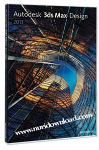
Autodesk 3ds Max Design 2013 Full Version Crack Patch Mediafire Download

Autodesk 3ds Max Design 2013 for 32bit and 64bit
Autodesk 3ds Max Design 2013 Full Version with Crack Patch from Mediafire free Download - Autodesk 3ds Max Design 2013 for 32bit and 64bit to add a graphic design software complete the admin adds Autodesk 3ds Max Design version 2013. Autodesk 3ds Max Design 2013 is a software rendering 3D models and animation to manufacturing, games and others. Autodesk 3ds Max Design 2013 has a feature that is more complete than Autodesk 3ds Max 2013. Additionally Autodesk 3ds Max Design 2013 has also been optimized compared to previous versions so that the process of rendering was noticeably faster and uses less computer resources. Curious sob?

Autodesk 3ds Max Design 2013

What is Autodesk 3ds Max Design 2013?
Autodesk 3ds Max Design 2013 is the most comprehensive software to process 3D modeling, animation, game development and graphic design

Features Autodesk 3ds Max Design 2013:
1. 3D rendering tools and the complete model
2. Rendering process optimization
3. Integrated with adobe after effects
4. Support system is 32 bit and 64 bit
5. And other exciting features sob

Download:

Extract password:  www.ad4msan.com


Friday, 11 October 2013

Cent OS


CentOS Overview

CentOS is an Enterprise-class Linux Distribution derived from sources freely provided to the public by a prominent North American Enterprise Linux vendor.  CentOS conforms fully with the upstream vendor's redistribution policy and aims to be 100% binary compatible. (CentOS mainly changes packages to remove upstream vendor branding and artwork.)  CentOS is free.

CentOS is developed by a small but growing team of core developers.  In turn the core developers are supported by an active user community including system administrators, network administrators, enterprise users, managers, core Linux contributors and Linux enthusiasts from around the world.

CentOS has numerous advantages over some of the other clone projects including:  an active and growing user community, quickly rebuilt, tested, and QA'ed errata packages, an extensive mirror network, developers who are contactable and responsive, multiple free support avenues including IRC Chat, Mailing Lists, Forums, a dynamic FAQ.

This site makes use of Javascript.  If your browser doesn't work with Javascript we recommend you use FireFox.
 

CentOS 6 Releases

March 12th 2013


The CentOS team is pleased to announce the immediate availability of CentOS 6.4 for i386 and x86_64 architectures.

CentOS 6.4 is based on the upstream release EL 6.4 and includes
packages from all variants. All upstream repositories have been combined into one, to make it easier for end users to work with.

There are some very important changes to this release compared with the previous versions of CentOS and we highly recommend reading this announcement along with the Release Notes. Especially take a look at the "Known Issues" section.

There is also a minimal install CD that will get you a very small base install that you can add to.

And now: Have fun.

Release Notes: CentOS
Download: i386 | x86_64


Download Link: